This section describes the way in which flow measurements using the Streamflow technique are entered into EDGE. It does not describe the technical method or provide a procedure for undertaking the measurements. However, in order to explain the data entry requirements it is necessary to provide a brief overview of the configuration of the work. This is shown in Figure X below. The methodology and procedures are provided through technician training.
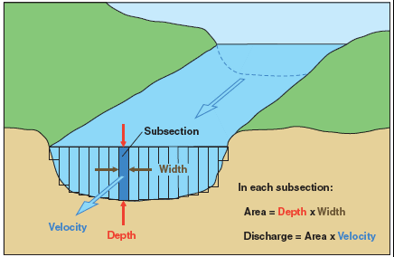
When undertaking Streamflow measurements a velocity is measured in a vertical ‘column’ of water. The measurement in this column requires information on:
Location Code (sys_loc_code)
Date/time
Flow calculation method
Station number
Width or interval (units of m)
Depth (units of m)
Velocity (units of m/s)
Subsection or interval flow (units of m3/s)
Technician
Equipment Code
Definitions are as follows:
1.Location Code – the location at which the flow measurement is being undertaken and will be provided in the EDGE file
2.Date and Time – date and time at which each sub section or interval velocity measurement is made
3.Flow Calculation Method – The code for the streamflow calculation is STREAMFLOW. This must be selected from the drop down list.
4.Station Number – Stations are numbered from one bank of the river based on the cumulative distance from the starting point on the bank. It is recommended that the starting bank to be used is the LEFT bank when FACING UPSTREAM. The first station would be at the distance of the first width or interval from the bank. So if the first subsection had a width of 0.5m, the station would be called Station 0.5. If the next interval is 0.5m the second station would be Station 1. The next subsection could have a width of 1.5m in which case the third station would be 2.5. The Station number should therefore be considered as the cumulative distance to the furthest edge of the current subsection from the starting point on the bank.
5.Width – This is the horizontal distance forming the width of the ‘column’ of water in which the velocity is being measured. Note that the width of subsection does not need to be the same for each subsection.
6.Depth – Is the average vertical distance from the stream surface to the stream bed across the width of the subsection.
7.Velocity – The value representing the velocity of the water column is the mean velocity of the water in the subsection, measured using a current flow meter. The method by which this number is derived is taught as part of the method training.
8.Interval Flow – The flow in each subsection is calculated as width(m) x depth(m) x velocity(m/s). The resulting flow value is in m3/s (metres cubed per second). This value is automatically calculated in the Flow_Measurement tab in EDGE as the Interval Flow. The Interval Flow units are provided in the adjacent column.
9.Technician – The name of the monitoring technician undertaking the work. Select from a drop down.
10.Equipment Code – The code of the current flow meter being used to undertake the measurements
Note: The EDGE Flow_Measurement tab has a number of columns. The different Flow Calculation methods require different columns and so there are more visible than are required for the method being described in this section. Only those columns listed above are required to be populated.
Data Entry Method
1.Select the location in the location pane (bottom left of EDGE screen)
2.In the Activity Tab there will be an entry requesting that this flow measurement method be used for the selected location.
3.For each new subsection flow measurement:
a.In the Flow_Measurement Tab click on the ‘New’ icon on the lowest tool bar
b.You will be prompted to select a task. Select the task containing the streamflow measurement requirement.
c.A new row will be added to the tab.
i.Date. The time will be automatically populated as the current time, so new measurements should be entered as they are made.
ii.sys_loc_code and sys_sample_code will be populated automatically
iii.Select ‘STREAMFLOW’ from the drop down list as the Flow Method
iv.Enter the station number (see above for description)
v.Enter Interval (width) of subsection. Note the Interval Unit defaults to metres and this unit must b used for all measurements
vi.Enter depth of subsection. Note the Interval Unit defaults to metres and this unit must b used for all measurements
vii.Enter velocity from the current flow meter. Note that the units are defaulted to m/s and entries of velocity must be in this unit
viii.The Interval Flow will be calculated and displayed automatically. The Interval Flow Units will be in m3/s
ix.Select technician name from the drop down list
x.Select the equipment code from the drop down list
xi.Enter any remarks in the remarks column. Remarks might include observations on the condition of the stream, presence and impact of vegetation and/or weed, obstructions etc.
d.Once the subsection flow detail has been entered completely, create a new row repeating each step above
4.Once all subsection flow measurements have been entered for the specified location on that day, go to the Flow tab.
5.In the Flow Tab,
a.check that there is a total flow measurement for the location at which the work has been done
b.Select the technician name from the drop down in the Technician column
6.In the Activity Tab there will be an entry requesting that this flow measurement method be used for the selected location. The date and time should be entered when the task is complete, and a Y entered in the result column. If the task could not be completed the result should be set to N and a reason provided in the remarks column.
7.This should complete all required flow work for the specified location in terms of the Activity, Flow Measurement and Flow tabs and there should be no remaining alerts.
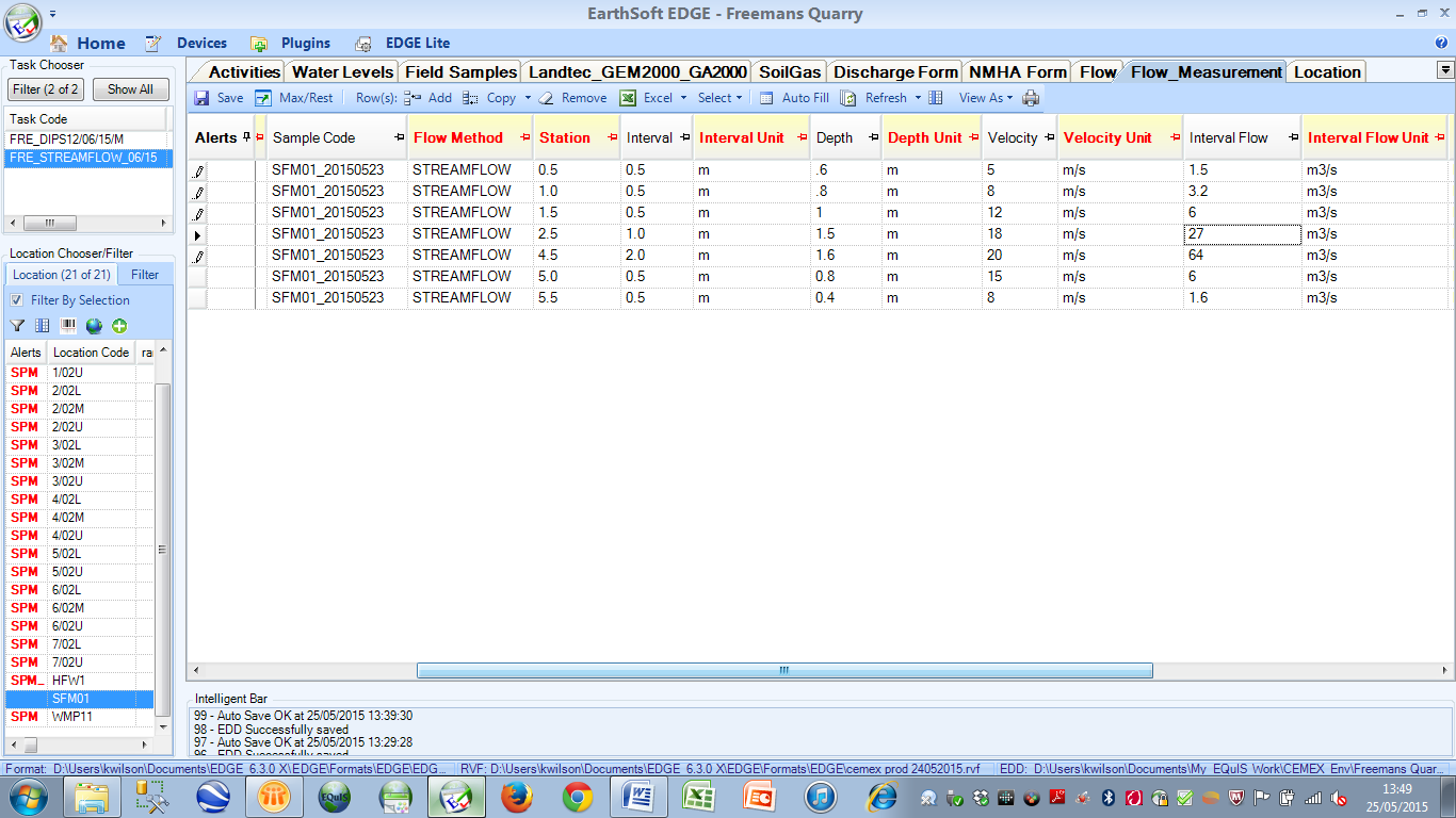
An example of a completed Flow_measurement tab is shown below.

The screen shot below shows the right side of the screen with Interval Flow values calculated automatically.